WARNING: You can damage or destroy your sound card by following any of these instructions. You as the reader assume all liability for any damage arising from trying to follow these instructions. If you don't want to take any chances then DON'T mess with your sound card.
The Problem: You just built a sweet new system and find out that your case's front panel audio and microphone jacks won't connect to your Audigy2 ZS sound card. You can't believe you spent all this money on a nice case and you can't use the front panel. There's no way in hell you're going to keep reaching around to the back of the case to switch the connector from your regular speakers to your headphones... that's just lame. You're also not going to go to RadioShack and get an audio jack splitter... that's just even more lame.
The Solution: Build your own audio connector to plug into the "special" Audigy2 ZS white connector. See the image below:
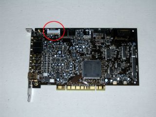
Some Background: (Skip this if you want.) As you can see this is a 10 pin connector. Searching the Internet with google yields a few clues as to the pinout. The DevHardware.com forums have a discussion, but it's unsatisfactory. The connector needed isn't identified (though there's speculation that it's a Dell OEM part.) Worst of all is that the .100 inch headers supplied by most case manufactures don't fit securely to the 2.0mm connector on the Audigy2 ZS board. People have to resort to tape and rubber band hacks to keep the headers in contact with the connector. A good start, but a problematic long term solution.
Is this connector a special OEM connector? No it can't be. There is no way that a volume PC peripheral manufacturer would ever use a non-standard or hard to find connector. The "white" connector on the Audigy2 ZS is no exception. It has to be cheap and easy to source. That said it should be available on the Internet somewhere.
So how did I find this connector? A friend lent me a pair of digital calipers and I started taking a bunch of measurements. I found that the pin spacing was 2.0mm. Then I did a lot of google searching that took almost a week. The breakthrough came when I found these parts at 4UConn. They looked very similar. Even better was that the site had two PDF files (1, 2) that gave the dimensions. Using the digital calipers I found what seemed to be a match. These connectors were meant as "equivalents" for the JST PH series connector. I then went to Digikey.com and checked. Bingo! DigiKey had the original JST PH connectors in stock.
Bill of Materials:
Order this from Digikey:
Obtain the following (at any electronics supply like Fry's or cannibalize an old cable):
Assembly Equipment:
One pair of wire strippers w/ cutting capability.
One pair of needle nose pliers.
One candle (for shrinking the heat shrink tubing).
Soldering iron and electrical solder (optional)
Permanent marker.
Magnifying glass (optional but recommended if you're over 35).
Assembly Procedure:
Step 1:
Get the Audigy2 ZS connector pinout. Here it is:
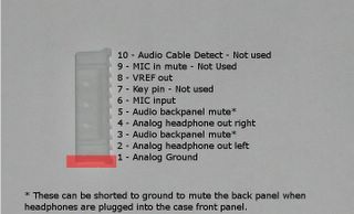
Use the permanent marker to color the end of the connector that is pin1. This will help a lot during assembly.
Step 2:
Cut the ethernet cable to the desired length. I have a very long front panel cable so I only needed something around 4 inches. I don't recommend less because it becomes hard to work with the cable.
Step 3:
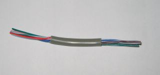
Strip off about one 1.25 inches of the outer cable case from each end of the ethernet cable. See below:
Step 4:
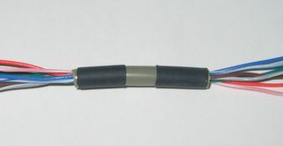
Cut two 1/2 inch (2cm) sections of the heatshrink tubing and slide them over the ends of the cable. See below:
Step 5:
Remove any extra conductors (wires) from the ethernet cable. (I pulled out a single wire.)
Step 6:
Strip off about 3mm of wire from each of the conductors on one end of the cable. This will be the side that goes to the Audigy2 ZS connector.
Step 7:
Begin to crimp the 455-1127-1-ND terminal pins onto the wires. This is where the needle nose pliers, magnifying glass and lots of patience come in handy. There really isn't an easy way to crimp the terminal. I've tried pre-bending the part that crimps to the insulator, but the results were mixed. Trial and error is all that works here. Just be sure to get the terminal crimped onto the conductor properly. Here is what I consider a good crimp/connection:
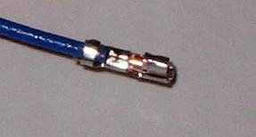
The first band is the crimp for the insulator. The second band is the crimp for the conductor. You should not have any insulator in the second crimp. Be extremely careful not to crush or damage the third part of the connector. That part is what accepts the blade from the Audigy2 ZS connector. If it's crushed or bent it won't mate properly.
When done you should have something like this:

Step 8:
You have two options here. One requires soldering and the other doesn't. Personally I chose the soldering one, but you should get good results either way. If you're not soldering then just strip off 4mm of insulator from all the conductors on the other side of the cable. Then crimp the WM2515-ND terminals onto the conductors in a similar fashion as described in step 7. A typical crimp will look like this:
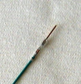
Notice that the conductor only goes a little past the second crimp. This works fine. However, I didn't go with it because I felt that the 24 AWG was at the lower end of what this crimp terminal would accept in terms of wire thickness. Couple that with the fact that I don't have a crimp tool for this connector and I was uneasy about the connection. I decided to solder. This is what that looks like:
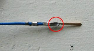
Two things to notice about this connection:
1. The wire has been pushed all the way to the end of the terminal. Right where the terminal narrows is where the wire stops. (Red circle area.) This conductor has been lightly soldered to the terminal here.
2. The crimps are both on the insulator now.
At any rate it's your choice.
Step 9:
Push the 2.0mm terminal pins (455-1127-1-ND) into the 2.0mm terminal housing (455-1151-ND) at the correct locations for your application. This will vary based on your case's front panel connector. At a minimum you will need to insert the Analog Ground, Analog Audio Left, Analog Audio Right, Microphone Input and Microphone VREF terminals into the terminal housing. The terminals only go in one way and lock into place with a tiny bump on the bottom. It should look like this:
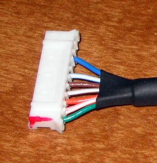
Notice that I've marked pin 1 with red marker to keep things straight. (I also got a little over zealous and shrunk the heatshrink tubing early. Resist the temptation to do this. You may need to switch the pins around and the heatshrink will be in your way. This happened to me because the mic input and vref were mislabeled on my case.)
Step 10:
Your cable/connector should now look like this:
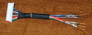
At this point you can test your cable by plugging the .100" pins into the proper places on your case's front panel cable. Then you can proceed to plug the other end into the Audigy2 ZS. Warning!!! If you mess this up or mix up pins you can fry your Audigy2 ZS. Do this at your own risk.
Step 11:
If everything in step 10 went well then you can put the .100" housing on the .100" terminal pins. The pins have to be oriented correctly so that the little latch tab latches onto the housing. You should be able to see the latch catch through the small square hole in the housing. See below:
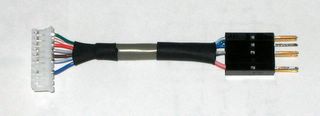
(Boy my soldering sucks. I guess you lose a little of your edge after 5 years.) Then just slide the heatshrink tubing over the ends of the cable housing. The heat of a single candle is enough to shrink the tubing into place.
Step 12:
Connect your new cable up to the Audigy2 ZS and your front panel. Enjoy having sound and a microphone jack on the front of your case:
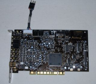
connected to the Audigy2 ZS...
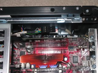
in the case with the front panel cable connected to our adapter...
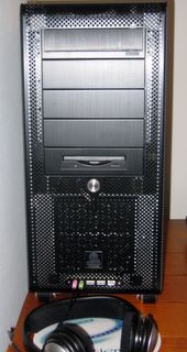
Step 13:
According to Brian Hitney the Audigy2 ZS will mute all microphone inputs into the board (this includes the one you just connected to the front panel) if there isn't a plug in the normal microphone jack on the card. So go get an old Walkman set of headphones and cut the plug off. Put that into the headphones jack and you should be in business.
TODO:
I've now got sound and microphone coming to the front of the case. However, I really wanted the speakers to mute when I plugged in the headphones. That isn't happening. I may need to make a shorting jumper between pins 1, 3, and 5 on the Audigy2 ZS connector. I thought (incorrectly) that if I connected the case cable's Left and Right return pins to the "mute" pins on the Audigy2 ZS connector that things would work. Oh well, it's still better than reaching around to the back of the case.
Feel free to post comments or suggestions for improvements. I'd really love to know if anybody with a Lian Li V1200(B) case got the muting to work.
UPDATE 1/11/2006:
After reading through the comments left by various readers I've decided to take another look at the 10pin header outputs on my Audigy2ZS. As I mentioned above, my speakers wouldn't mute when I plugged my headset into the front panel. I've since upgraded my old speakers to a new pair of Klipsch 2.1 speakers. The problem now is that they will mute if I unplug my headset. So I've definitely got something wrong in terms of pinout.
I've also experienced the microphone not behaving properly. Had a done a little more investigation I'd have noticed what has been pointed out in the comments: that the VRef for the mic isn't 5V, but 2.5V. This isn't enough to properly power the mic and you will get muted or garbled sound when you speak.
So what to do? Well more investigation. (I'm also open to more suggestions from readers/users of this blog.) Eventually, if I get it figured out I'll update the blog with new diagrams and pictures. Until then stay tuned and keep the comments coming.
Thanks!
Update 7/21/2006:
I just want to say thanks again to all the posters who've added valuable comments to the site. I check this blog pretty infrequently and it's nice to pop in and see that people have really improved my instructions. I need to digest some of what's been said here before I try it on my rig. Work has been a bear so I've been satisfied with my hacko setup for the time being.
Thanks again everyone!
Update 4/19/2007:
Apologies to all the people who've been expecting me to update the instructions. Life has intervened and I'm just not able to get to it. The comments section is full of good advice from a variety of contributors who've taken this humble project much further than I ever intended. Unfortunately I've had to turn off anonymous comments because of the idiotic spam that gets posted to the page. It's simple enough to register for a blogspot account so I hope this doesn't act as a barrier to people who want to post good solutions to issues regarding the Audigy.
The Problem: You just built a sweet new system and find out that your case's front panel audio and microphone jacks won't connect to your Audigy2 ZS sound card. You can't believe you spent all this money on a nice case and you can't use the front panel. There's no way in hell you're going to keep reaching around to the back of the case to switch the connector from your regular speakers to your headphones... that's just lame. You're also not going to go to RadioShack and get an audio jack splitter... that's just even more lame.
The Solution: Build your own audio connector to plug into the "special" Audigy2 ZS white connector. See the image below:

Some Background: (Skip this if you want.) As you can see this is a 10 pin connector. Searching the Internet with google yields a few clues as to the pinout. The DevHardware.com forums have a discussion, but it's unsatisfactory. The connector needed isn't identified (though there's speculation that it's a Dell OEM part.) Worst of all is that the .100 inch headers supplied by most case manufactures don't fit securely to the 2.0mm connector on the Audigy2 ZS board. People have to resort to tape and rubber band hacks to keep the headers in contact with the connector. A good start, but a problematic long term solution.
Is this connector a special OEM connector? No it can't be. There is no way that a volume PC peripheral manufacturer would ever use a non-standard or hard to find connector. The "white" connector on the Audigy2 ZS is no exception. It has to be cheap and easy to source. That said it should be available on the Internet somewhere.
So how did I find this connector? A friend lent me a pair of digital calipers and I started taking a bunch of measurements. I found that the pin spacing was 2.0mm. Then I did a lot of google searching that took almost a week. The breakthrough came when I found these parts at 4UConn. They looked very similar. Even better was that the site had two PDF files (1, 2) that gave the dimensions. Using the digital calipers I found what seemed to be a match. These connectors were meant as "equivalents" for the JST PH series connector. I then went to Digikey.com and checked. Bingo! DigiKey had the original JST PH connectors in stock.
Bill of Materials:
Order this from Digikey:
Quantity: Part Number: Description: Price:Please note that these are minimum quantities. You will likely need more of the terminal pins since it's very easy to bend/break them when crimping them to the wires. You can also change the 10 position .100" housing to be a different configuration of 10 pins. I chose the WM2522-ND 10 position .100" DUAL connector because my case used that type from the front panel. If your case has a front panel cable that breaks out each pin then the choice is largely aesthetic. I suggest ordering triple the pins you need and double the housings.
100* 455-1127-1-ND CONN TERM CRIMP PH 24-30AWG $3.43
1** WM2522-ND CONN HOUSING 10POS .100 $1.01
10 WM2515-ND CONN TERM MALE 22-24AWG GOLD $1.44
10* 455-1151-ND CONN HOUSING PH 10 POS 2MM WHITE $0.85
-----------------------------------------------------------------------
Parts Sub-Total: $6.73
Order under $20 Fee: $5.00
Shipping (USPS Priority Mail) $3.95
-----------------------------------------------------------------------
Total: $15.68
*This is the minimum quantity that can be ordered.
**This is a 2x5 header. If you need a different part then please look at the
catalog page and find the one that fits your requirements.
Obtain the following (at any electronics supply like Fry's or cannibalize an old cable):
45cm (18") of CAT5 ethernet cable.I used the ethernet cable because for two reasons: I had it lying around, and it contains eight 24AWG wires in assorted colors. 24 AWG is what the two types of terminal pins will both accept as well. For my application I only needed seven conductors (actually less) so ethernet was perfect.
5 inches of 5mm (.20") heat shrink tubing
Assembly Equipment:
One pair of wire strippers w/ cutting capability.
One pair of needle nose pliers.
One candle (for shrinking the heat shrink tubing).
Soldering iron and electrical solder (optional)
Permanent marker.
Magnifying glass (optional but recommended if you're over 35).
Assembly Procedure:
Step 1:
Get the Audigy2 ZS connector pinout. Here it is:

Use the permanent marker to color the end of the connector that is pin1. This will help a lot during assembly.
Step 2:
Cut the ethernet cable to the desired length. I have a very long front panel cable so I only needed something around 4 inches. I don't recommend less because it becomes hard to work with the cable.
Step 3:
Strip off about one 1.25 inches of the outer cable case from each end of the ethernet cable. See below:

Step 4:
Cut two 1/2 inch (2cm) sections of the heatshrink tubing and slide them over the ends of the cable. See below:

Step 5:
Remove any extra conductors (wires) from the ethernet cable. (I pulled out a single wire.)
Step 6:
Strip off about 3mm of wire from each of the conductors on one end of the cable. This will be the side that goes to the Audigy2 ZS connector.
Step 7:
Begin to crimp the 455-1127-1-ND terminal pins onto the wires. This is where the needle nose pliers, magnifying glass and lots of patience come in handy. There really isn't an easy way to crimp the terminal. I've tried pre-bending the part that crimps to the insulator, but the results were mixed. Trial and error is all that works here. Just be sure to get the terminal crimped onto the conductor properly. Here is what I consider a good crimp/connection:

The first band is the crimp for the insulator. The second band is the crimp for the conductor. You should not have any insulator in the second crimp. Be extremely careful not to crush or damage the third part of the connector. That part is what accepts the blade from the Audigy2 ZS connector. If it's crushed or bent it won't mate properly.
When done you should have something like this:

Step 8:
You have two options here. One requires soldering and the other doesn't. Personally I chose the soldering one, but you should get good results either way. If you're not soldering then just strip off 4mm of insulator from all the conductors on the other side of the cable. Then crimp the WM2515-ND terminals onto the conductors in a similar fashion as described in step 7. A typical crimp will look like this:

Notice that the conductor only goes a little past the second crimp. This works fine. However, I didn't go with it because I felt that the 24 AWG was at the lower end of what this crimp terminal would accept in terms of wire thickness. Couple that with the fact that I don't have a crimp tool for this connector and I was uneasy about the connection. I decided to solder. This is what that looks like:

Two things to notice about this connection:
1. The wire has been pushed all the way to the end of the terminal. Right where the terminal narrows is where the wire stops. (Red circle area.) This conductor has been lightly soldered to the terminal here.
2. The crimps are both on the insulator now.
At any rate it's your choice.
Step 9:
Push the 2.0mm terminal pins (455-1127-1-ND) into the 2.0mm terminal housing (455-1151-ND) at the correct locations for your application. This will vary based on your case's front panel connector. At a minimum you will need to insert the Analog Ground, Analog Audio Left, Analog Audio Right, Microphone Input and Microphone VREF terminals into the terminal housing. The terminals only go in one way and lock into place with a tiny bump on the bottom. It should look like this:

Notice that I've marked pin 1 with red marker to keep things straight. (I also got a little over zealous and shrunk the heatshrink tubing early. Resist the temptation to do this. You may need to switch the pins around and the heatshrink will be in your way. This happened to me because the mic input and vref were mislabeled on my case.)
Step 10:
Your cable/connector should now look like this:

At this point you can test your cable by plugging the .100" pins into the proper places on your case's front panel cable. Then you can proceed to plug the other end into the Audigy2 ZS. Warning!!! If you mess this up or mix up pins you can fry your Audigy2 ZS. Do this at your own risk.
Step 11:
If everything in step 10 went well then you can put the .100" housing on the .100" terminal pins. The pins have to be oriented correctly so that the little latch tab latches onto the housing. You should be able to see the latch catch through the small square hole in the housing. See below:

(Boy my soldering sucks. I guess you lose a little of your edge after 5 years.) Then just slide the heatshrink tubing over the ends of the cable housing. The heat of a single candle is enough to shrink the tubing into place.
Step 12:
Connect your new cable up to the Audigy2 ZS and your front panel. Enjoy having sound and a microphone jack on the front of your case:

connected to the Audigy2 ZS...

in the case with the front panel cable connected to our adapter...

Step 13:
According to Brian Hitney the Audigy2 ZS will mute all microphone inputs into the board (this includes the one you just connected to the front panel) if there isn't a plug in the normal microphone jack on the card. So go get an old Walkman set of headphones and cut the plug off. Put that into the headphones jack and you should be in business.
TODO:
I've now got sound and microphone coming to the front of the case. However, I really wanted the speakers to mute when I plugged in the headphones. That isn't happening. I may need to make a shorting jumper between pins 1, 3, and 5 on the Audigy2 ZS connector. I thought (incorrectly) that if I connected the case cable's Left and Right return pins to the "mute" pins on the Audigy2 ZS connector that things would work. Oh well, it's still better than reaching around to the back of the case.
Feel free to post comments or suggestions for improvements. I'd really love to know if anybody with a Lian Li V1200(B) case got the muting to work.
UPDATE 1/11/2006:
After reading through the comments left by various readers I've decided to take another look at the 10pin header outputs on my Audigy2ZS. As I mentioned above, my speakers wouldn't mute when I plugged my headset into the front panel. I've since upgraded my old speakers to a new pair of Klipsch 2.1 speakers. The problem now is that they will mute if I unplug my headset. So I've definitely got something wrong in terms of pinout.
I've also experienced the microphone not behaving properly. Had a done a little more investigation I'd have noticed what has been pointed out in the comments: that the VRef for the mic isn't 5V, but 2.5V. This isn't enough to properly power the mic and you will get muted or garbled sound when you speak.
So what to do? Well more investigation. (I'm also open to more suggestions from readers/users of this blog.) Eventually, if I get it figured out I'll update the blog with new diagrams and pictures. Until then stay tuned and keep the comments coming.
Thanks!
Update 7/21/2006:
I just want to say thanks again to all the posters who've added valuable comments to the site. I check this blog pretty infrequently and it's nice to pop in and see that people have really improved my instructions. I need to digest some of what's been said here before I try it on my rig. Work has been a bear so I've been satisfied with my hacko setup for the time being.
Thanks again everyone!
Update 4/19/2007:
Apologies to all the people who've been expecting me to update the instructions. Life has intervened and I'm just not able to get to it. The comments section is full of good advice from a variety of contributors who've taken this humble project much further than I ever intended. Unfortunately I've had to turn off anonymous comments because of the idiotic spam that gets posted to the page. It's simple enough to register for a blogspot account so I hope this doesn't act as a barrier to people who want to post good solutions to issues regarding the Audigy.

114 Comments:
Great Blogg
I live in the UK, but with a bit of cash spent, Digi-key (Thanks for the part no's I wouldnt have had a clue) delivered from the States in 4 days. Took your advice about odering extra bits but all has gone smoothly. My crimping etc is not as neat as yours but the results are fine. I have a CM Stacker case and my mic works best in pins 6 & 7! Oh and I do not need a blank plug in the mic rear socket to make it work.
Thanks again, great stuff.
This issue has been bugging me for months and finding your complete set of instructions with photographs was great news. D'you fancy making one for me!? HA! HA! Only joking! Seriously now your blog is excellent and should be up front in a prominent position somewhere!
Thanks Again, Peter
I was wondering if you ever modified your cord so that it mutes the speakers when you plug in the headphones (i.e. short pins #3 and #5 to ground).
Thanks for making a great page with lots of useful info.
Dan Healy
San Francisco, CA
It's really amazing!!
After reading your full instruction, I hope to try to make one for my Lian-Li case. Unfortunately, I cannot find the plug here in HK.
Ronny
I found a 2mm connector and trimed it down from 22pin to 10pin. It fits perfectly to the Audigy 2 ZS white connector. I am using Lian-Li PC-3077. From the info provided, I can match 5 pins for connecting the white connector with the Lian-Li front panel. However, I see that there are 7 connections. What are the 2 left behind? Where should they be connected?
How to make the speakers mute when I plugged in the headphones?
Thanks very much.
Ronny
very nice.....Im gonna try it this weekend...
Just wanted to let you know that the part number for the black connector that you list, from DigiKey.com, is the wrong part. That if for a 1x10 housing. The correct part number is WM2522-ND. This is that part number for the 2x5 housing. I found this out the hard way, when my package arrived today from DigiKey:(
Hmm. About you not getting the speakers to mute when you plugged in your headphones, I believe pin 3 and pin 5 to be incorrect. I say this because pin 3 on my audigy 2 ZS card is pumping out 2.5 volts. Pin 8 also pumps out 2.5 volts...leaving me to believe that is where my missing 2.5 volts were for my mic at pin 8. What do you think?
Not positive about the Audigy2zs, but on the X-Fi XtremeMusic tying pins 3 and 5 together will make the software mute everything on the back panel (ie. your speakers) and reconfigure the software for headphone output. Nice guide, btw. I looked all over Digikey for those parts =).
Anyone who visits and leaves a comment hoping for help/assistance
please add e-mail address.
TO the guy that said "the X-Fi XtremeMusic tying pins 3 and 5 together will make the software mute everything on the back panel"
What exactly does this mean? I have an X-Fi and orderd all the parts - but I ain't no electrician?? Help please?
Shortcipher@gmail.com
quote:
1 - Analog Ground
2 - Analog Headphone Out Left
3 - Audio Backpanel Mute -- short to ground to mute the backpanel (when headphones are plugged in)
4 - Analog Headphone Out Right
5 - same as #3
6 - Mic input from front panel
7 - key pin (shouldn't be there)
8 - VREF out -- voltage reference for Mic
9 - MIC IN MUTE -- ground when mic isn't plugged in, +12VDC when mic is plugged in
10 - Audio cable detect -- will be ground when headphones are plugged in (not normally used)
Has anyone tried connecting pin 10 to 3/5? Pin 10 returns a ground when headphones are in and 3/5 require a ground to mute the back, so does it work?
There is a market if someone either sells these pre-made or makes up some kits to sell on eBay.. I'd buy one.
As has been mentioned many times, mic input does not work properly due to only having 2.5V.
A simple solution is to solder a header on the card connected to the +5V backplane connector and attach your front panel connection there instead.
Not what I wanted, but works fine.
For what it is worth, I'd pay $30USD for one of these that worked.
I bet a lot of others would too.
I went for it, but my aspire case had way to much noise for mic or headphones, but I did use pins 2 and 4 to connect with the red and orange case wires to make my VU meter bounce to the music ;)
This is a terrific page. Congratulations and my best wishes to you. For my own needs, I don't need the rear speaker muted when headphones are plugged in, but I do need the microphone to work well. There must be an easier/more elegant way to get this to work besides soldering on the Audigy! What you really need to do is find someone with a Dell who has got this working and see what is going on with that. SoundBlaster Inc. are acting like nimrods about this. Even if I were willing to pay for their front panel gizmo (i'm not) it's ugly. Plus you have to use those converter plugs. And if you have a door on your case, then you have to leave the door open just to use the hookups (meanwhile your nicely integreated front panel stuff is not usable). Lame of them. By the way, I would also pay good money for this cable of yours. Maybe you could write the people at FrontX to make one like it, once you get the kinks worked out :)
Following the pinout i posted above, I started playing around with them today. I found out you can have the entire output backpanel muted with these pinouts:
1 - ground
2 - front right
3 - front right
4 - front left
I haven't tested anything with the mic yet, but it seems to not work properly. Give it a try and let me know if it works.
i also tried to connect my frontpanel and my mirc does not work, too.
also it does not work to mute backpanle when mic plugged in.
i started to check the pinout voltages and got this result:
Pin -> Voltage
1 -> 0
2 -> 0.03
3 -> 3.2
4 -> 0.03
5 -> 0
6 -> 0.2
7 -> 0
8 -> 2.5
9 -> 0
10 -> 0
perhaps someone knows wich votage the Mic_bias needs?
i alos found a +5v on the ad_ext port.. i will tets ist tomorrow
The part numbers don't work any more on Digikey.com. Can i get an updated list..
Thanks
I've checked the part numbers from the page and they are still correct for Digikey. However, the links to the PDF files are not. I will remove them because I don't feel like updating them every time Digikey releases a new catalog (which is quarterly).
I figured out why the rear speakers won't mute when the headphones are pluged in.
I have a Dell Dimension 8200, and when you plug in the front headphones, the plug closes a connection that sends pins 3 and 5 to ground.
Currently, on my new computer, and any others that use the standard 2x5 motherboard connector for the front mic and headphones, when you plug in the headphones, you actually open the connection that goes from the onboard sound to the outputs on the back of your motherboard. When there is no plug inserted, the signal goes straight thru the headphone plug.
It seems to be a slightly different type of plug used on the Dell's than what comes on most other cases.
I have looked, but can not find the plugs anywhere except eBay (and only if you buy a Dell front I/O board).
Hope this info helps
Why short 3 and 5 to ground? You should short pins 3 and 5 to pin 10. Pin 10 is designed so that it will be ground when the mic is pluged in and will be open when the mic is not plugged in. Therefore if you take 3 and 5 to ground, it will mute the back panel audio when the front panel mic is plugged in.
Also I think the Mic In Mute is supposed to be +12VDC when the mic is plugged in? A carefully placed resistor could give you the 5VDC you need there for the mic.
"Why short 3 and 5 to ground? You should short pins 3 and 5 to pin 10. Pin 10 is designed so that it will be ground when the mic is pluged in and will be open when the mic is not plugged in. Therefore if you take 3 and 5 to ground, it will mute the back panel audio when the front panel mic is plugged in."
- Anonymous
That doesn't work, try it.
"I figured out why the rear speakers won't mute when the headphones are pluged in.
I have a Dell Dimension 8200, and when you plug in the front headphones, the plug closes a connection that sends pins 3 and 5 to ground.
Currently, on my new computer, and any others that use the standard 2x5 motherboard connector for the front mic and headphones, when you plug in the headphones, you actually open the connection that goes from the onboard sound to the outputs on the back of your motherboard. When there is no plug inserted, the signal goes straight thru the headphone plug.
It seems to be a slightly different type of plug used on the Dell's than what comes on most other cases.
I have looked, but can not find the plugs anywhere except eBay (and only if you buy a Dell front I/O board).
Hope this info helps"
- Anonymous
I figured as much. I'd suggest taking your front panel apart and adding two wires that connect pins 3 and 1 together on the Audigy. Then take the other end of the wires and attach them into the headphone socket plug on the front panel. Then when you plug in your headphones, the headphone plug will close the connection and mute the backpanel.
Now, as for the mic voltage problem. You could always plug that into the mic voltage pin on your motherboard.
To fix your power problem without soldering:
You'll need three things: a motherboard with a front panel audio header, a one pin connector (like the ones used to connect led + and - to your motherboard), and one wire. If you have a spare CD-Rom audio cable that will work perfectly, otherwise you can use Cat 5 or whatever else you used to wire the rest of the project. The nice thing about the audio cable is that it is already crimped, and if you don't have any one pin connectors the three pin connector can be trimmed down (neat edges don't matter, just clip off a couple of the holes).
If you're using the audio cable, remove the three wires on each end from the block. Clip off two, it doesn't really matter which two as long as you keep the same colored wire on both ends. Now you have one long pre-crimped wire. Otherwise make yourself a wire with the Cat 5 cable and crimp both ends with a large terminal connector.
Remove (or don't connect) wire number 8 from your Audigy block. You'll also want to remove that same wire from the black connector. Take your new wire and plug one end into the same spot on your black connector.
Plug the other end into either MIC_BIAS or MIC_VCC on your motherboards front panel audio header. You should pay attention to which power source your case intended to be used. If you compare the plug that came with your case, to the audio front panel header diagram in your motherboard manual, you can see whether or not the case intended to get power from MIC_BIAS or MIC_VCC.
Viola, a power work around that doesn't require any soldering.
Oh and just to answer another question I saw repeatedly: For those of us who are simply rewiring the end of the wire that came with our case, instead of making a two ended connector.... the two extra wires most people will have are Right return and Left return, which are not used in this project.
Justin Proulx
@Home PC Repair
Gloucester, VA
P.S. Great article... I found it by the credit in Maximum PC. Good job!
These are being sold ready-made on eBay now... For those who would rather buy than build...
Search for audigy harness.
That's a great article. I am trying to make an improvement of your cable for the connecting issue. Do you know the name of that 9-pin receptacle which is sitting on the motherboard to connect the front audio connector (WM2522-ND). I checked the guide book of my motherboard, it says it's called 10-1 pin AAFP connector, but I could not find it anywhere. Do you have any idea of that? Please contact me at youyou4343@gmail.com
ThankX!
Steven
Winnipeg, Canada
Hi
i just pluged mic in to pin 6
ground to pin 1 and mic_pwr to pin 3
noch i hear the mic perfect
Possibly a cheaper way to go is by using a connector (cable already attached ;-) ) from the inside of a used mouse. The connectors there are usually 5 Pin JST PH type.
Also, if you are dead-set on a 10-pin find a trackball (specifically a NSI model).
See: http://www.nsi.be/Pinning_trackballs.PDF
can you tell me now ?
it is work all on Audigy2value too
Please tell me Thank you so much
As for the backpanel mute on connecting headphones (tried it on x-fi): 1) Pin 10 doesn't work as expected (I don't know why- the little bugger) as well as any other pin configuration. Pin 3 shortened to any of "ground" pins does the trick but you have to do it manually unless: 1)you buy a special 4 "channel" mini-jack socket (couldn't get one in Poland though and didn't want to break my walkman;)) 2) There is a "do it yourself" way I devised today incorporating an aluminium pad, 20cm of cord and a bit of glue though it would be hard for me to explain in simple words :)(works really fine and costs almost nothing) if you're interested I'll make a step by step guide publish it on the web and place a link here - Lucas
"i just pluged mic in to pin 6
ground to pin 1 and mic_pwr to pin 3
noch i hear the mic perfect"
This causes the rear speaker port to go dead (regardless whether anything is connected in front).
As far as muting the back panel and WHY it WILL NEVER work with the PC case based headphone jack.
Some of the folks who posted here are on the right track, but here is the skinny. ALL of the PC case based 1/8" standard phono jacks use OPEN CIRCUIT style jacks, with 3 conductors (ie, R/L and Gnd) This is standard for nearly ALL types of audio, except for those that MUTE !!!!
These tend to use whats called CLOSED CIRCUIT connectors/jacks. These have and ADDITIONAL 2 poles that SHORT 2 other circuits when the plug is inserted, and this handles shunting the pin 3/5 wires to ground, which causes the Audigy to shut off the back panel.
These are $3 parts at any electronic store, and you need to use them if you want an auto mute of the back panel. BUT.... you can also use a single throw, 2 pole switch to manually shunt those wires as well. Not that elegant, but it gets the job done....
I think that the Large AD_EXT connector in the Audigy cards accomodates for this, but the pinouts available are confusing :(
Hope this helps.
I'm not sure if you ohmed out the front panel connections before to figure out how you can enable the rear channel mute function, but here is the info i gathered:
headphones NOT plugged in:
l/r_Return -> l/r_Out = short circuit (~4.4 ohms)
l/r_Return -> gnd = open circuit
l/r_Out -> gnf = open circuit
headphone plugged in:
l/r_Return -> l/r_Out = open circuit
l/r_Return -> gnd = open circuit
l/r_Out -> gnf = ~46 ohms (speaker coil)
I just realized their are some errors in the previous comment (i had posted it a few days ago). Today I got my parts to make the cable from digikey, and while trying to figure out how i can utilize the mute pins of the SB A2ZS I relized my mistake. With the headphone unplugged the R/L_Return is ~46 ohms, close enough to ground the mute. So if we were to connect it to the mute pins (3/5) it would cause the backpanel speakers to mute, w/ no head phones plugged in = no sound. If we plug in the headphones, the R/L_Retern floats (not grounded anymore), so the mute pins (3/5) are no longer grounded - now we have sound on both the headphones and back panel speakers. This is the opposite of what we need... but we have something that toggles when headphones are plugged in and removed. So i came up with a little circuit from some parts I had laying around in order to invert the signal of the R/L_Return. It uses only 3 components: 2 resistors and a NPN Switching transistor (PN2222A). here's a link to a schematic of my circuit:
http://img220.imageshack.us/img220/2338/mutecircuitbx8.jpg
http://img220.imageshack.us
/img220/2338/mutecircuitbx8.jpg
I just created this in the past hour or so, and so far it is working great. hopefully things stay working great :)
Woops, that should be pins 3/5 for mute in my schematic
in case anyone doesnt want to spend the cash to buy the parts. you can get samples from molex and jst on their websites.
Anonymous said...
I just realized their are some errors in the previous comment (i had posted it a few days ago). Today I got my parts to make the cable from digikey, and while trying to figure out how i can utilize the mute pins of the SB A2ZS I relized my mistake. With the headphone unplugged the R/L_Return is ~46 ohms, close enough to ground the mute. So if we were to connect it to the mute pins (3/5) it would cause the backpanel speakers to mute, w/ no head phones plugged in = no sound. If we plug in the headphones, the R/L_Retern floats (not grounded anymore), so the mute pins (3/5) are no longer grounded - now we have sound on both the headphones and back panel speakers. This is the opposite of what we need... but we have something that toggles when headphones are plugged in and removed. So i came up with a little circuit from some parts I had laying around in order to invert the signal of the R/L_Return. It uses only 3 components: 2 resistors and a NPN Switching transistor (PN2222A). here's a link to a schematic of my circuit:
http://img220.imageshack.us/img220/2338/mutecircuitbx8.jpg
http://img220.imageshack.us
/img220/2338/mutecircuitbx8.jpg
I just created this in the past hour or so, and so far it is working great. hopefully things stay working great :)
10:33 PM
Anonymous said...
Woops, that should be pins 3/5 for mute in my schematic
11:31 PM
THIS would be awesome info but alas I connot see or get to you images :o(
A question about MIC 5v power: can you connect the MIC Tip (power cable) to 5v off of the Case's PSU 5 volt instead of Pin 8? If so, would you need to connect the ground to the PSU or would Pin 1 be ok?
Also, has anyone had luck with shorting Pins 3,5,and 10 to get automatic back pannel shutoff?
Jason
jazz_inc at yahoo
the link to my image stick works, the format of the blog messes up the url though.. you just gotta put the url together from these 2 parts:
http://img220.imageshack.us/
img220/2338/mutecircuitbx8.jpg
you could probably just use a inverter too (7404). that is the reason for the transistor in my schematic
Ok I doctor stupidhead here figured out the picture...
Does this scematic work ???
Does it work when there is no Vcc signal ( audio signal ) coming from the sound card ???
Does it have to be connected to both returns ???
Has there been any " amp shorting " as a result ???
sorry for all the questions but awesome circuit as i was thinking along teh lines of amosfet triggering a relay or something
Hey man, great site and instructions. Thermaltake Matix case and audigy 4, mic works great along with headphones. To all with mic issues, I've found that some cases with front audio do not have a connection for mic power. I matched the vref (pin 8) to the mic power and all works great. Thanks for making life somewhat more convenient.
Haven't been on this page for a while but I've had a working solution for a long time. Although not perfect, it just requires a mic to be plugged in to have the backpanel muted properly.
When I plug in a mic, speaker profiles switch to headphones and everything is good.
Just get a damn Dell case and check, or ask Turtle Beach, who supply the Santa Cruize to Dell with the same connector.
I bet TB will tell you if you ask nicely.
These aren't on eBay anymore, but there's now a website where you can buy them ready-made: http://harness.gadgetscope.com/
Just FYI, that site, http://harness.gadgetscope.com/ looks like the way to go. Also, they mentioned that having 'Automatically mute speakers when headphones are detected' with the pin config that we've talked about will cause the speakers to be constantly muted or muted when headphones ARENT plugged in... so uncheck that feature.
Kindly let me know, if the same is applicable to the Live 24-bit cards.
If it has the 10-pin header (I think they are all white), then all of this is applicable to you. Just look at it to see if it does.
Even if it doesn't though, you could still clip on some wires to the solder points on the back of the chipset and make a proper male pin housing for your female pin case headphone jack.
http://harness.gadgetscope.com
Thanks for this link!
I built a unit with some resistors and a mosfet. it works great . mutes automatically when the plug is inserted and everything :o)
cost me $12.00 in parts
Hi, sorry for my english
I have the X-Fi connector (WM2522-ND CONN HOUSING 10POS) but if you can´t found the connector you can use the old cd-rom audio cables.
See the link the (the white connector)
http://images.google.es/imgres?imgurl=http://www.sfcable.com/Merchant2/graphics/00000001/11A1-B1.jpg&imgrefurl=http://www.sfcable.com/store/11a1-b1.html&h=257&w=316&sz=6&hl=es&start=15&tbnid=7_rs07FUelLLLM:&tbnh=95&tbnw=117&prev=/images%3Fq%3Dcd-rom%2Bsound%2Bcable%26svnum%3D10%26hl%3Des%26lr%3D%26sa%3DG
Saludos
Rad-Wulf
The Link
http://www.sfcable.com/catalog/
wholesalecables/11A1-B1.html
Rad-Wulf
i was just wonderind how you figured out what the pins on the audigy did... i would appreciat if anyone could tell me how you can figure something like that out without a hell load of luch
sorry i ment to say luck :)
An amazing site so with great source of information.
_____________________________
http://www.workerbees.biz/images
mmm..I have my speakers and hearphones working, I connected the pin 3 and 5 with 1 and nothing happened, my speakers continue working, how I can mute the backpanel?
Thanks to you !
would this work with an "sb live" card?
I hate these stupid spammers !!!
Hmm... I have a suspicion that the header is the same as an Intel HD Audio header, the specs for which can be found at http://www.formfactors.org/developer%5Cspecs%5CA2928604-005.pdf
Of interest is page25, which (if you ignore the fancy EMI filter block) basically shows a few interesting things.
First, you have to connect a 1kohm resistor to ground for one of the pins, probably the Audio Cable Detect (pin 10) This should enable the X-FI card to recognize it is connected to an Intel HD audio spec front audio port.
... That's as far as I've gotten so far. If anyone else wants to further examine this, it might prove helpful.
Okay, another interesting tidbit. A comment about making a pull-up circuit to invert the FP_Return signals was on the money... the AC97 spec uses normally closed, non-isolated switches in the jacks, and the Intel HD audio spec uses normally open, isolated switches. Unfortunately, while nearly all motherboard manufacturers have adopted the HD audio spec, almost none of the case manufacturers have.
PS: This is all re: pages 20-25
http://www.formfactors.org/developer%5Cspecs%5CA2928604-005.pdf
http://harness.gadgetscope.com/
there you can buy the cable. i don't know if they work and they seem to be really expensive, but maybe someone will give it a try (i surely won't).
For all you folks having problems with your front panel audio, making front panel mic's work, etc., realize there is two very different hardware front panels as detailed from above poster - HD compliant and AC97 compliant. Most case makers supply an AC97 compliant front panel. Although you can 'sort of' make a AC97 compliant front panel work, it will be a bastardized setup that will forever drive you nuts, just like all the comments above as well as spread all over the Internet. The absolute simple solution is to just buy a SILVERSTONE SST-FP32 aftermarket front panel for $13 from newegg that slips into one of your 3.5" drive slots:
http://www.newegg.com/product/product.asp?item=N82E16813999356
As you'll read, it supports both the AC97 and HD front panel specifications (use on cable or the other).
Make your life easier and just disconnect your old case front panel connections and plug these in and your HD compliant Audigy (or any other HD compliant sound card for that fact) will work just as it should.
P.S. - want to know all about HD and AC97 audio standards, and I mean everything? Start right here and ALL your questions will be answered:
http://www.intel.com/support/motherboards/desktop/sb/cs-020642.htm
And one more very important document specifically about front panels:
http://www.formfactors.org/developer/specs/A2928604-005.pdf
And here's a pin-out pic of that SILVERSTONE SST-FP32 aftermarket panel that pretty clearly shows how different the pin-out between the AC97 and HD standards are:
http://sundialmicro.com/images/products/items/fp32-pin.jpg
I got my x-tap cable yesterday.
everything ok except for the fact it won't mute the backpanel.
I checked the option in the audioconsole but it won't matter.
Not a bigdeal, Ill just power off my speakers.
Higly satisfied with the cable from
http://x-tap.com/
i can recommended this to everyone who doesn't want to make this cable him/her self
For those with an Audigy 2 without the white front panel connector (as circled in the authors article) but you do have the solder holes for it, you can add it with Digikey part 455-1727-ND. Minimum order is 10, but at ~ $3 total it's no big deal.
This is the information I've been looking for, but I need a little help.
I'm trying to connect not to the case per se, but to an Aerocool Coolpanel 2. The Coolpanel has a mic/headphone cable (an odd 6-pin job). The headphones and mic each have 3 wires with single-pin plugs on the end that's supposed to go on your mobo (but in this case modified to Audigy).
The pins on the headphone part are labeled R, L, and Gnd - easy enough. The mic is labeled R, L, and Gnd also - which confused me. I don't know which to connect to mic in, and which to connect to VREF pin.
Any thoughts?
Thanks for the guide
Is there anywhere that sells this adapter ready made? Im desperate for one, but my skills are no where good enough to make this
What you need to mute the back speakers is a DPDT-NO mini jack. That is a mini jack that has built in double pole, double throw, normally open contacts. You would connect the normally open contacts to the two Audigy back panel mute control wires (p3 & 5) on that white connector block. With the ground (p 1 & 10) going to the shield/ground of the jack and the Lft (p3) and Rt (p4) going to contacts for the tip (lft) and ring (rt) of the headphone plug.
You should be able to find these jacks pretty easily, try Moser or some one like that. They should be standard size for the hole they will attach to, only thing would be the depth, probably.
Hope that helps.
If someone still hangs with muting the back speakers: I've got a case with HD-Audio connectors (see standards). There you have to connect pin7 (from HD Front Panel Audio) to pin3 (white connector block audigy or x-fi) and pin10 (HD Audio) to pin5 (Audigy or x-fi). I think Doane meant the same and I did it this way with my HD Front Panel Audio connectors and X-Fi extreme music. It works great!!! In the creative console ->headphones the two checks have to be set. Now when plugged in only rear audio mutes and audio settings change automatically to headphones. ~1h soldering saved ~80€!!
Wow spam on your blog? how rude.
Great stuff I am about to order my parts from digikey I'm doing an X-FI Fatality version.I have the breakout box but it doesn't play well with games. I thought I would replace the opamps as well while I have the soldering gear out.I'll post on the sucess of my efforts soon.
I originally read about your blog in MaximumPC
badders: x-tap.com
Great stuff guys! I think for this purpose I will even BUY me an Audigy2 ZS even though I do not yet have one!
I currently have a 1999/2000-built Creative Live! Value which works great, but which does not seem to have the requirements needed for building an appropriate cable.
Buying this thing plus the cable from x-tap will leave me at about $70 incl. shipping.
Normally, an X-Fi card without this great cable will already be at about $60 so it does look a bargain to me!
I found a way to get the back panel speakers to mute on the XFI without using jumpers, transistors, resistors, or grounding any extra wires to each other. The answer is very simple. Just use this layout:
1-GND
2-Phones L
3-MIC BIAS
4-Phones R
5-RET L
6-MIC
7-X
8-X
9-X
10-X
I have been using this setup for over a week now but there is a bit of noise while I have micboost on and that's annoying. I have been checking my card everyday though and it's not shorting anything out. I was tinkering around with setting RET R to pin 8 and it got rid of the hissing but I need to test that a bit more. I will update later tonight.
This comment has been removed by the author.
LOL, I feel dumb now. All I really needed to do was turn off mic boost. No need for an extra wire. I am still currently using the pun out I have diagrammed above. By this way. This only works if you plug in both the headphones, and mic. Shouldn't be a problem for those of us with headsets. Which is probably most of us.
Thanks this info very help...
But, I have some question is Audigy2 ZS connector pinout same with Audigy value connector???
Need Your Help,
EMIL - Indonesia
Thank you for this article. I had wondered if there was a way to connect the Audigy cards to the now-standard front panel jacks of my various boxes. Oddly enough, I own a Cooler Master Stacker (a magnificent beast!) and the USB mainboard-to-front panel cables seem to use the connector that you described in the project. They also are cut to ten pin length so I'll try one on the white connector and see if it's a go-er. I don't use the USB FP connectors and the CMS has an Audigy Platinum so that leaves me three to play with. Also too, the Audigy's driver has an option to mute the speakers when headphones are detected. Is that option in place? I could go on but I won't *g*. Thanks again for the write-up.
Hey, great tutorial. I'd just like to point out that you can in fact get all the parts on digikey for FREE, by requesting samples from the manufacturers.
The card header housing and pins are from a company called JST (www.jst.co.uk), part numbers PHR-10 and SPH-002T-P0.5S.
The socket housing and pins are from Molex (www.molex.com), part numbers 16-02-0115 and 22-55-2101.
I have received my samples from JST already and have filled a request on molex. Its possible that I may have been approved since I used my own domain name for my email address, but its worth a try!
If I remember, I shall post back when I have made and tested the cable, reporting any troubles I may have :p
Mike (UK)
A quick update: I'm not sure about what to do over the MIC input, but just to confirm to people wondering about headphone muting, with the HD audio connector the pins marry up thusly:
X-Fi / Audigy -> HD Audio
1 -> 2 GND
4 -> 5 PORT 2R
3 -> 6 SENSE1_RETURN
2 -> 9 PORT 2L
5 -> 10 SENSE2_RETURN
I've currently got bare wires pushed in the HD Audio header to check pin outs. Also, HD Audio specifies left and right channels for the microphone, not VREF and one channel!
Many thanks for identifying a suitable connector for the creative card though!
Is your diagram for the HD connector comming from the front panel or the pins on the board?
It matches my mobo pin placement so shouldn't it be mirrored for the connector? The black (usually ground) wire for my HD connector is on the right, same side as the plugged key pin, opposite of your diagram.
Thanks for researching Creative's proprietary pinouts and learning how to create a way to make the front audio panel work.
I have an X-Fi Fatal1ty Pro card and an Antec 900 case. I have managed to get the front audio panel to work properly for both headsets and microphone.
Instead of building my own harness, I bought one from Performance PC's.
http://www.performance-pcs.com/catalog/index.php?main_page=product_info&cPath=83&products_id=21700
I don't know if it's just the adapter cable that I received or if they are all this way, but I noticed that they crossed the 2 black wires at the AC'97/HD connector. Pin #1 is supposed to be Mic Input and Pin #2 is supposed to be ground. After tracing the wires to the Creative proprietary connector, I found that they were crossed. It is easy to extract the pins from the AC'97/HD connector, but you must be very careful when pulling up on the pin retainers because they are made of thin plastic and don't flex very much and can break.
Just a minor detail, but I noticed that there is a pointer on the AC'97/HD connector that is supposed to indicate the location of Pin#1. This pointer is on both male and female connectors and is supposed to align when both connectors are plugged together, so you know that it is connected right. Obviously, when they assemble these connectors, they don't pay attention to the pointer. So make sure you connect it the right way.
So to sum up the cable adapter, it does work! It works for both the headphones and microphone jack! Now the catch. I found out that it does not work very well with the AC'97 connector for my Antec 900 case, even though it says it was made for AC'97. The right side audio did not work on my headphones when it was plugged into the AC'97 connector. But if you plug it into the HD connector, it works great. I'm glad that the Antec 900 case comes with both types of connectors. So make sure you have an HD connector.
When plugging in the headphones to the front panel, it does mute the rear speakers. To get this to work you have to open the Creative control panel, under "Headset" tab, check the box to mute the rear speakers when headset is plugged in. I believe you have to close it and restart the computer for it to take affect. If you don't restart the computer, the rear speakers will not mute.
When first plugging in the microphone to the front panel, the volume is really low. I had to talk really loud to barely hear my voice through the headphones. Many people have complained about this. But, after some fiddling around I found that it can be set to a higher volume. Here is how make it work with the X-Fi Fatal1ty card in XP:
1. Open the X-Fi Creative Console Launcher (Game Mode) and go to Mixer. Max out the microphone volume.
2. Go to Windows Control Panel. Select Sound, Speech, and Audio Devices. Select Sound and Audio Devices. Select Audio tab. Select Volume under the sound recording section. It opens a new window with various slider controls. Max out the Microphone volume slider. Select Options and make sure Advanced Controls is checked. Select Advanced button. Select the checkbox for "1 Microphone +20dB Boost."
3. Do a check on the microphone and you should be able to hear yourself without talking excessively loud. There is a Test Hardware function in the Voice tab that you can perform.
Is anyone currently selling these (I'd be willing to pay)? I'd rather pay someone to do it right because I have very little electronic assembly skill.
Bio Hazard,
Did you read the previous post?
Thank you so much for the pin out on the Audigy 2 ZS card...invaluable! Thank you thank you thank you!
I am using it on my xtrememusic. I didnt care about the muting of the speakers, I just manually turn the volume to the speakers. I didnt feel it was a big deal compared to pulling out my tower everytime i wanted to use my headphones.and then pulling it out again to switch it back to the speakers.
I have enough to make more cables if anyone is in need of one and doesnt have access to the parts.
paulvirc@personainternet.com
This comment has been removed by the author.
Nice guide. Does anyone know if that premade cable from performance pcs works with the audigy 4? It doesn't say which models it works for.
Michael,
Yes, it should work with the Audigy 4. The sound card has the same pinouts as the Audigy 2 and the X-Fi XtremeGamer Fatal1ty Pro, which are both now outdated. Make sure you swap the two black wires though. Apparently Performance PC builds them all the same way.
Ok, for any UK residents I found this site in the UK:
http://uk.farnell.com/
They take american express, visa or mastercard as payment.
The order codes are:
1463043
1462530
1671245
3616265
1st of all, congrats, yout tutorial continue to be the most complet and nice on the internet. I found some new clues for help this tutorial.
After furter search I found the 10pin conector not only are Dell-OEM but follows the Intel HD Audio CODEC rules (http://www.intel.com/support/motherboards/desktop/sb/CS-015851.htm) and (http://www.intel.com/support/motherboards/desktop/sb/CS-020642.htm#standards)
so the 2.5v are not mic ref but the presense signal send.
Most front-panels are follows AC97, that is incompatible with Intel HD Audio. :(
I found the manual to assembly front panels, they describe matrials and schematics and a tip on using AC97 on Intel Audio without the sense-send (+2.5V)
www.formfactors.org/developer%5Cspecs%5CA2928604-005.pdf
nice blog i m visit your blog and really nice comment and use full for me... please add my post thanks
build a niche store
This comment has been removed by a blog administrator.
This comment has been removed by a blog administrator.
This comment has been removed by a blog administrator.
I hope this finds someone well. I didn't find it in the comments, but then again I didn't look too hard. The sound blaster card I have is an Audigy SE (SB0570). In order to get the Mic to work I had to move the wire from pin 8 to pin 10 on the sound car. Everything else was left the same.
is it compatible to first gen Audigy?
By the way, great job. Thx.
Just one question I don't know if its been answered yet. How do I know if I buy one of these plugs the configuration of the pins on the black side of the wire match up with my pc's front audio plug wire config. (HP xw6200)
Solved the problem
When your speakers don't shut up when you put your headphones in, but instead switch off the speakers when you pull out your headphones, really annoying!
The problem isn't with the connectors, It's in the headphone jack. After trying all different types of cable connections i got down to the conclusion. (You need your soldering iron for this task) I started to look inside the 3,5mm jack. Stupid fuck who made this Construction..
If you got 2 left, 2 right and 1 GND solders, you need to take out 1 of the 2 middle pins from inside, dont just snap it. Take it off the board and open it carefully.
If you looking at the solders with the jack pointing down i took off the middle one to the right, and the other one at the left in middle did i connected to pin3, working perfect!
leave pin5 empty. (I think pin5 are for your rear mic mute) why should pin3 have a twin brother? and it's three sound out in the back, so thats not logical.
Thanks for the valuable info you have here, You made my day and many days after!
If you guys don't want to build yourself it is available on ebay for 5 bucks (NOT 20 like on some other online store). Search for "Front panel audio adapter cable For creative sound card". The link which will probably expire soon: http://www.ebay.ca/itm/Front-panel-audio-adapter-cable-For-creative-sound-card-SB0220-SB0240-SB0670-/261210380251?pt=US_Cables_Snakes_Interconnects&hash=item3cd15a17db
I know this thing is old but I think that someone may need. For the pinout above I've just find out that it not correct and lack off some pins.
Just take a SB0880 and SB0770 then you will see. Although it has an Intel HD audio standart but it still has old 10pin header there, so it is very simple to take a meter and figure out which pin should go.
1...Ground
2...Port 2 left
3...Sense 2 Return
4...Port 2 right
5...Sense Send
6...Port 1 left
7...NC
8...Port 1 right
9...Sense 2 Return
10..Presence
i love reading this article so beautiful!!great job!
surround sound headsets
A caliper is a device used to measure the distance between two opposite sides of an object. A caliper can be as simple as a compass with inward or outward-facing points. The tips of the best digital calipers 2017 are adjusted to fit across the points to be measured, the caliper is then removed and the distance read by measuring between the tips with a measuring tool, such as a ruler.
Componentbuy is one of the fastest growing distributors of Semiconductors and electronic Components in the world.
Supports more than 20 Millions of Electronic components sourcing needs with Engineering Data support. Locating all your required components for your design and production needs.
Our website will act as tool for the sourcing and Design engineers on the components needs.
Quote
A quick turnaround time personalized quote ensures to meet your business critical needs.
Warehousing
Logistics and E-commerce to meet diversified needs of Original Equipment & Design Manufacturer,Electronic Manufacturing Services and Small and Medium Enterprises.
Scheduled orders will be accepted which in turn reduce yours warehouse management activities.
Technical and Customer support
Get real-time help from a Technical, Application and Customer support specialist over the Web. You get efficient, personalized support.
Alerts and notification
Upload the BOM under the BOM upload we will notify you the information on product changes and cross-reference products.
Get subscribed to our newsletter or the product notification and receive an alerts on the Product change notifications, Datasheets and lifecycle updates on the products.
What can we do for you ?
Our Engineers and Sales professionals helps customers to get their jobs done and get their products to market quickly and efficiently.
www.componentbuy.com
Judi Online
Judi Bola
Slot Online
i am regular reader, how are you everybody? This post posted at this site is truly good.
Sharkoon B1 Headset in UAE, Stereo Headset in UAE, Headset in UAE
https://gccgamers.com/sharkoon-b1-stereo.html
Sharkoon Headset in UAE, Safe Shopping Multiple Payment Options Express Delivery GCC Gamers Moneyback Guarantee.
1632283210865-11
Sharkoon B1 Headset in UAE, Stereo Headset in UAE, Headset in UAE
https://gccgamers.com/sharkoon-b1-stereo.html
Sharkoon Headset in UAE, Safe Shopping Multiple Payment Options Express Delivery GCC Gamers Moneyback Guarantee.
1632290497205-7
I am from hk.
It work but i don't have the plug. (someone in hk say i can't find the plug.)
so i did this shit:
https://www.reddit.com/r/pcmasterrace/comments/q75udu/creative_24_live_sound_card_creative_proprietary/
Post a Comment
<< Home